|
|
Modbus Master Protocol Configuration Section

This information applies to latest revision.
This driver is made by the two modules: modbus_driver.dll and modbus_master.exe
This driver maps modbus data formats to IEC data types using the following mapping:
| Register type | Function | Modbus_type | iec_type | offset |
|---|
| Holding Register, Analog Input, Read | 3 | VT_I4 | M_IT_TB_1 | 40001 |
| Holding Register, Analog Input, Read | 3 | VT_UI4 | M_ME_TO_1 | 40001 |
| Holding Register, Analog Input, Read | 3 | VT_R4 | M_ME_TF_1 | 40001 |
| Holding Register, Analog Input, Read | 3 | VT_R4SWAP | M_ME_TF_1 | 40001 |
| Holding Register, Analog Input, Read | 3 | VT_I2 | M_ME_TE_1 | 40001 |
| Holding Register, Analog Input, Read | 3 | VT_UI2 | M_ME_TQ_1 | 40001 |
| Holding Register, Digital Input, Read | 3 | VT_DP | M_DP_TB_1 | 40001 |
| Holding Register, Analog Output, Write | 16 | VT_I4 | C_BO_TA_1 | 40001 |
| Holding Register, Analog Output, Write | 16 | VT_R4 | C_SE_TC_1 | 40001 |
| Holding Register, Analog Output, Write | 16 | VT_R4SWAP | C_SE_TC_1 | 40001 |
| Holding Register, Analog Output, Write | 16 | VT_I2 | C_SE_TB_1 | 40001 |
| Input Register, Analog Input, Read Only | 4 | VT_I4 | M_IT_TB_1 | 30001 |
| Input Register, Analog Input, Read Only | 4 | VT_UI4 | M_ME_TO_1 | 30001 |
| Input Register, Analog Input, Read Only | 4 | VT_R4 | M_ME_TF_1 | 30001 |
| Input Register, Analog Input, Read Only | 4 | VT_R4SWAP | M_ME_TF_1 | 30001 |
| Input Register, Analog Input, Read Only | 4 | VT_I2 | M_ME_TE_1 | 30001 |
| Input Register, Analog Input, Read Only | 4 | VT_UI2 | M_ME_TQ_1 | 30001 |
| Coil, Digital Input, Read | 1 | VT_BOOL | M_SP_TB_1 | 00001 |
| Coil, Digital Output, Write | 5 | VT_BOOL | C_SC_TA_1 | 00001 |
| Input Status or Discrete Input, Digital Input, Read Only | 2 | VT_BOOL | M_SP_TB_1 | 10001 |
where
VT_I4 is a 32 bits signed integer
VT_UI4 is a 32 bits unsigned integer
VT_R4 is 32 bits float
VT_R4SWAP is 32 bits float with words swapped
VT_I2 is a 16 bits signed integer
VT_UI2 is a 16 bits unsigned integer
VT_BOOL is a bit
Step 1:
Creation of modbus protocol configuration database
Go to C:\scada\bin and run protocol_configurator.exe
For each device create a modbus database and a SCADA Unit.
A SCADA Unit corresponds to a SCADA line.
Example: For the device connected on line 1 create the database named modbus_database1.db and save it in C:\scada\project
For the device connected on line 2 create the database named modbus_database2.db and so on
Line 1 corresponds with the first Unit created, line 2 with the second Unit created and so on
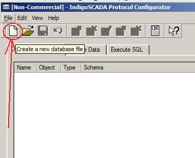
Create modbus_database1.db
|
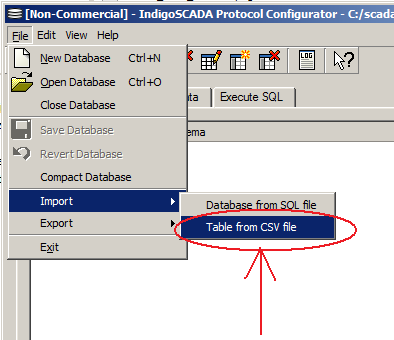
Select the import table menu. Import modbus_table.csv
|

Imported modbus_table.csv
|
Step 2:
Creation of the new SCADA points
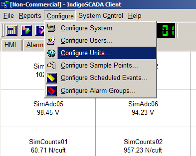
1 - Select the menu: Configure\Configure Units
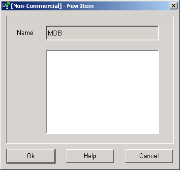
2 - Press button New
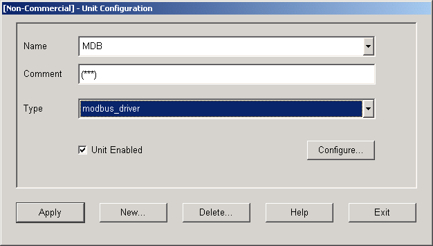
3 - Fill in the edit field Name: MDB
4 - Select Type modbus_driver, flag Unit Enabled and press Configure button
5 - Fill in the Modbus slave IP address, TCP port, number of points and Update Intervall in milliseconds for MODBUS TCP.
6 - Fill in the serial device, baud, data bits, stop bit, parity, number of points and Update Intervall in milliseconds for MODBUS RTU.
7 - Press button Apply and wait that the Apply button returns active and then press Exit
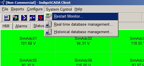
8 - Restart monitor.exe
9 - Monitored sample points are now visible
Step 3:
Configure each sample point
8 - Select the menu: Configure\Configure Sample Points
9 - Set Comment, Type, Units and the limits of each new point. Press button Apply
- Set type M_SP_TB_1 for digital point
- Set type M_ME_TC_1 for analog point
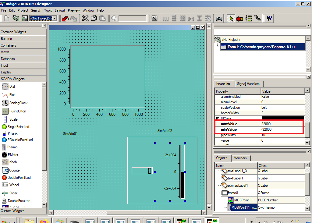
10 - Open HMI designer, select the widget and edit the maxValue and min Value
11 - The corresponding HMI object, here MDBPoint11, get the new maxValue and min Value.
Step 4:
HMI configuration with HMI designer
10 - Run the process C:\scada\bin\hmi_designer.exe
11 - Create from scratch your HMI (dialog) and save it as hmi0.ui in C:\scada\project
12 - Use the following widget classes
| Widget | Class
|
| SINGLE POINT LED | PSinglePointLed
|
| DOUBLE POINT LED | PDoublePointLed |
| SINGLE POINT LED | SinglePointLed |
| DOUBLE POINT LED | DoublePointLed
|
| SWITCH | PSwitch
|
| THERMOMETER | QwtThermo
|
| LCD NUMBER | PLCDNumber |
| COMMAND BUTTON | QPushButton |
| TANK | PTank |
| THERMOMETER | PThermometer |
| EDIT FIELD | QLineEdit |
| BREAKER | Breaker |
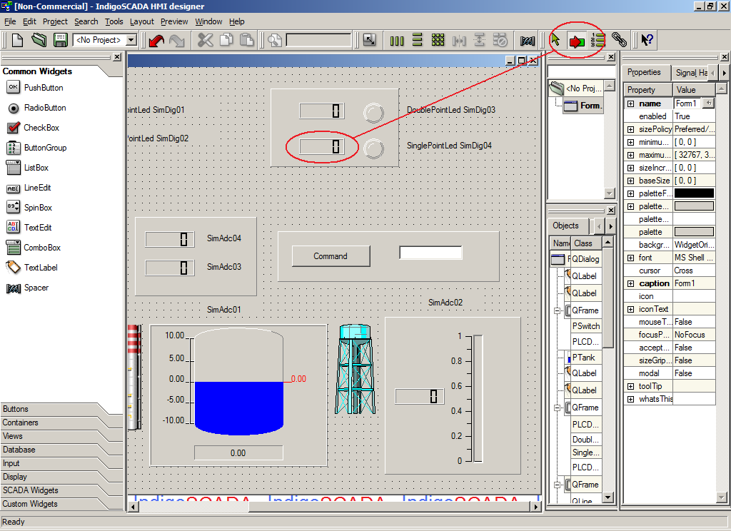
13 - Widget names MUST contain the underscore _ as separator between sample point SCADA name and widget ID
For example the widget with SCADA name MDBSample09 and ID 1 has full name: MDBSample09_1
Please see next image 1
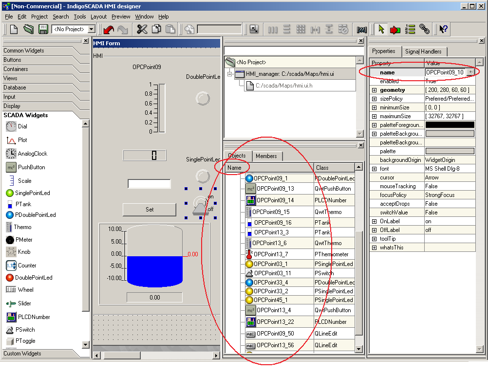
1
|
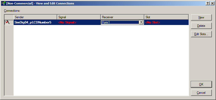
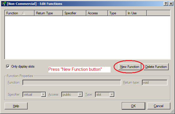
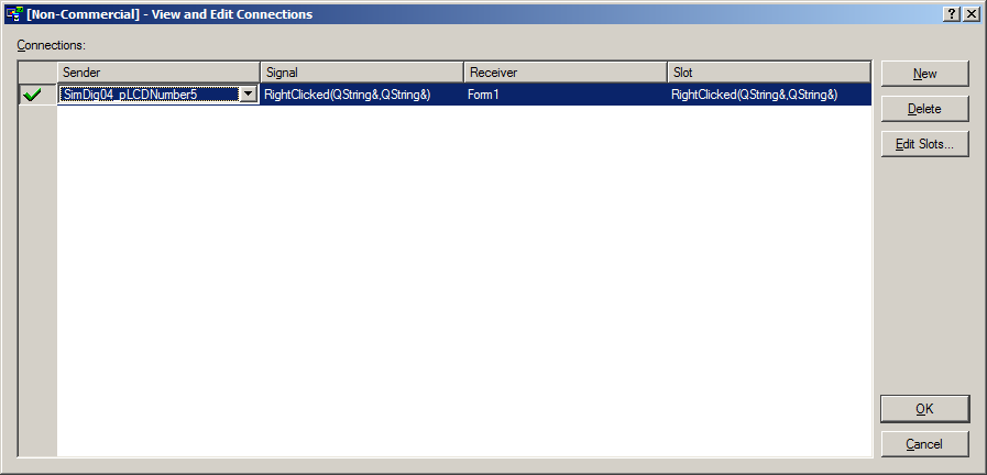
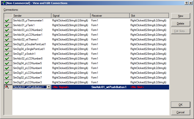
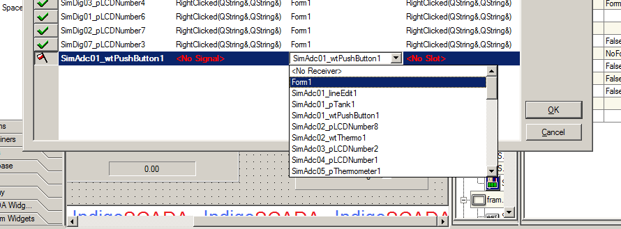
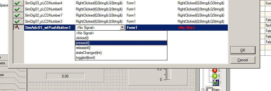
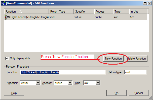
14 - To enable the inspect popup window, please follow the procedure:
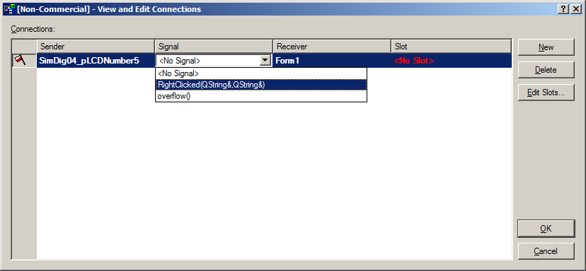
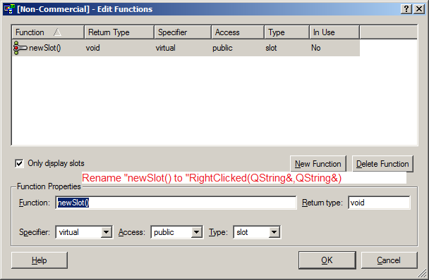
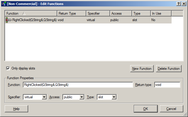
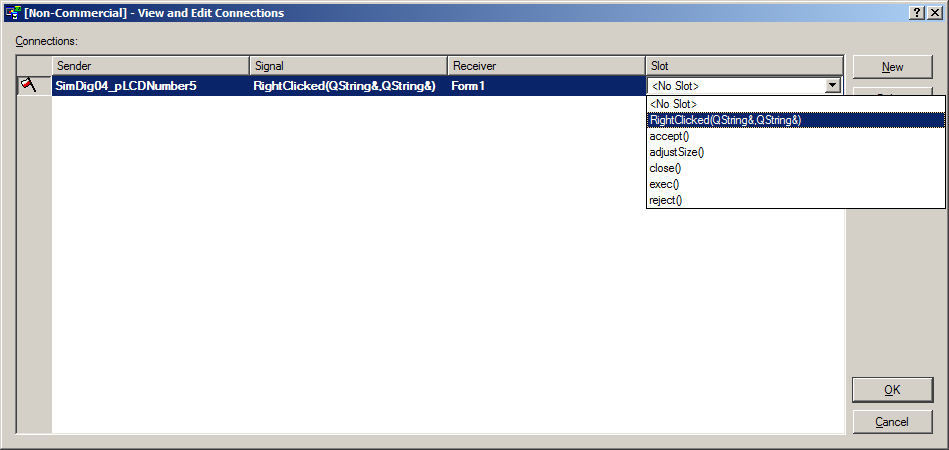
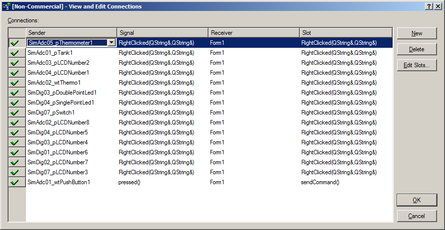
You have to connect the signals RightClicked(QString&,QString&) of the widgets with the slot RightClicked(QString&,QString&) of the HMI dialog (here Form1)
Step 1
|
Step 2
|
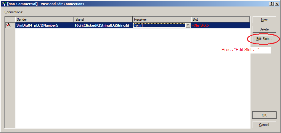
Step 3
|
Step 4
|
Step 5
|
Step 6
|
Step 7
|
Step 8
|
Step 9
|
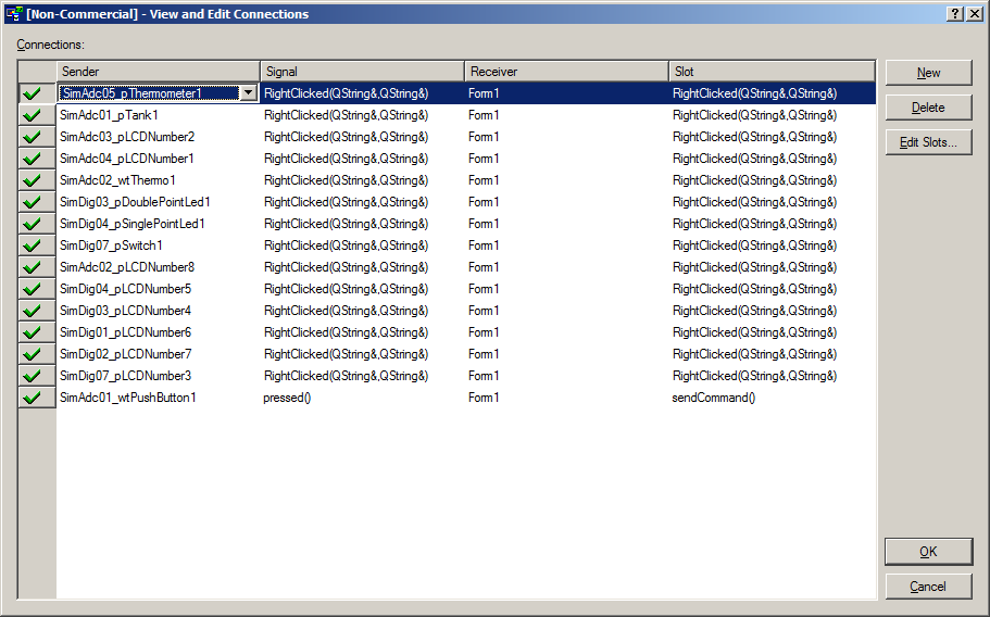
Final result
|
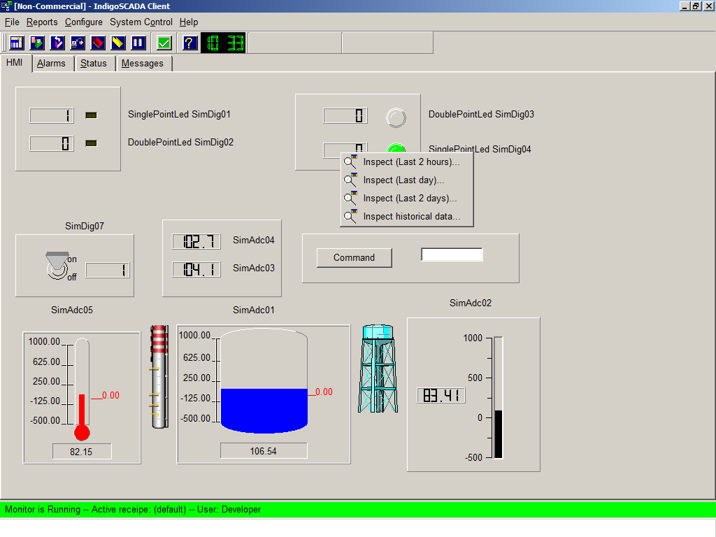
Working popup on HMI
|
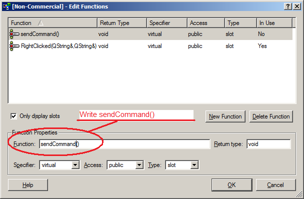
15 - To enable commands, please follow the procedure:
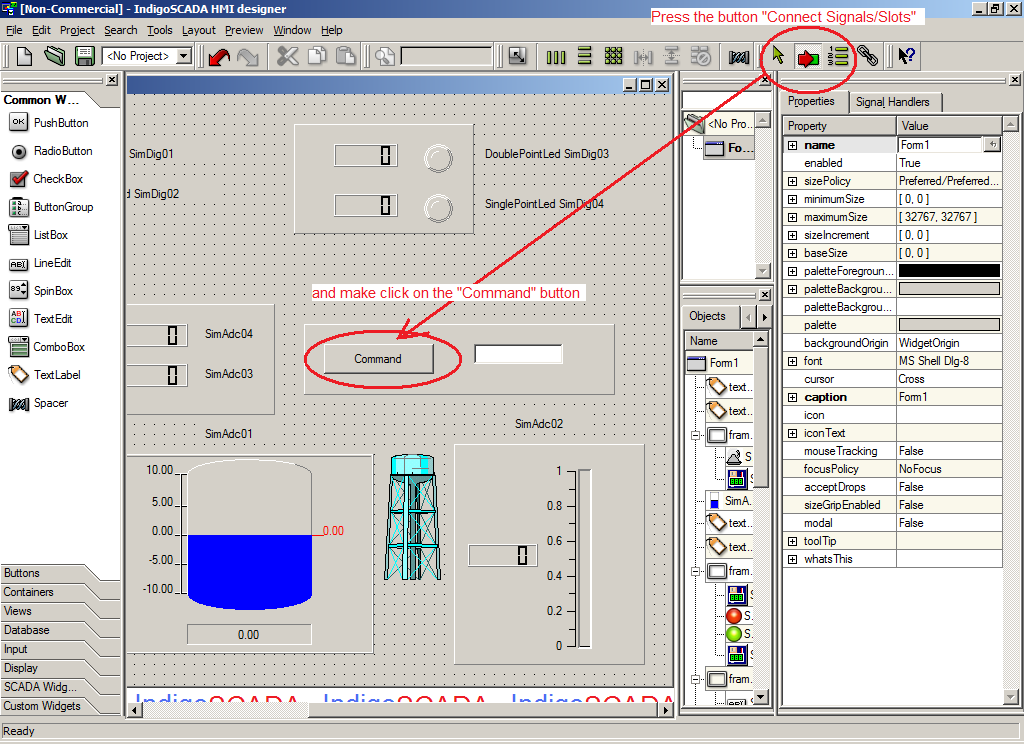
Step 1
|
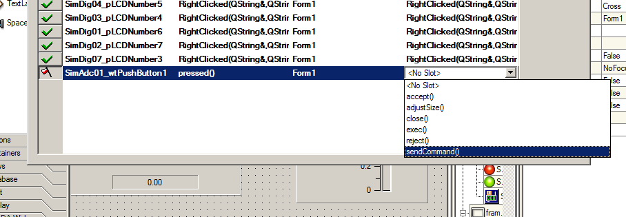
Step 2
|
Step 3
|
Step 4
|

Step 5
|
Step 6
|
Step 7
|
Step 8
|
Step 9
|
Swap of word in float number
Test with float NOT swapped
slave_id = 1
modbus_function_read = 3
modbus_function_write = 16
modbus_address = 0
modbus_type = VT_R4
ioa_control_center = 10
deadband = 0
[00][01][00][00][00][06][01][03][00][00][00][02]
Waiting for a confirmation...
<00><01><00><00><00><07><01><03><04><41>
modbus_read_registers: Get float: -1868585380923580700000000000000000.000000
The next test is with SWAP of float WORD
slave_id = 1
modbus_function_read = 3
modbus_function_write = 16
modbus_address = 0
modbus_type = VT_R4SWAP
ioa_control_center = 10
deadband = 0
[00][01][00][00][00][06][01][03][00][00][00][02]
Waiting for a confirmation...
<00><01><00><00><00><07><01><03><04><41>
modbus_read_registers: Get float: 23.370468
 - FloatConverter IEEE754 - FloatConverter IEEE754
|
|
|