MQTT Driver Configuration Section


The information in this document applies to latest revision.
This native driver is made by two modules: mqtt_client_driver.dll and mqtt_client.exe
Manual configuration:
Step 1:
Configuring MQTT Topics
Open a command shell windows and run the command, that will create the file configuration_file.sql in C:\scada\project:
cd C:\scada\bin
mqtt_client.exe -a broker_host_name -p # -e configuration_file.sql -q user -r pwd -l 1 -t 1883
The MQTT payload has to be encoded with Sparkplug B
Example:
C:\scada\bin>mqtt_client.exe -a broker.hivemq.com -p # -e configuration_file.sql -q user -r pwd -l 1 -t 1883
Step 2:
Creation of protocol configuration database
Go to C:\scada\bin and run protocol_configurator.exe
Import the C:\scada\project\configuration_file.sql, selecting the C:\scada\project\configuration_file.sql with the menu: File->Import->Database from SQL file
At the question: Do you want to create a new database file to hold the imported data?
Answer: Yes
The database name should be your broker_host_name with extension .db
Save it in C:\scada\project
If you do not use broker_host_name.db name, the Step 3 will fail.
Example: broker.hivemq.com.db
Wait for few seconds the Import Completed confirmation Window
Step 3:
Creation of the new SCADA points
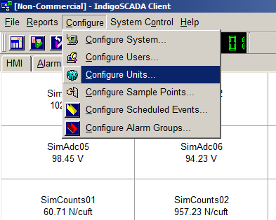
1 - Select the menu: Configure\Configure Units
2 - Press button New
3 - Fill in the edit field Name: MQTT
4 - Select Type mqtt_client_driver, flag Unit Enabled and press Configure button
5 - Fill in broker host name, subscribe topic name, number of Items.
6 - Press button Apply and wait that the Apply button returns active and then press Exit
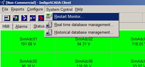
7 - Restart monitor.exe
Step 4:
Configure each sample point
8 - Select the menu: Configure\Configure Sample Points
9 - Set Comment, Type, Units and the limits of each new point. Press button Apply
- Set type M_SP_TB_1 for digital MQTT point (i.e VT_BOOL type or any scada point that evaluate to 0 and 1)
- Set type M_ME_TC_1 for analog MQTT point
8
|

9
|
Step 5:
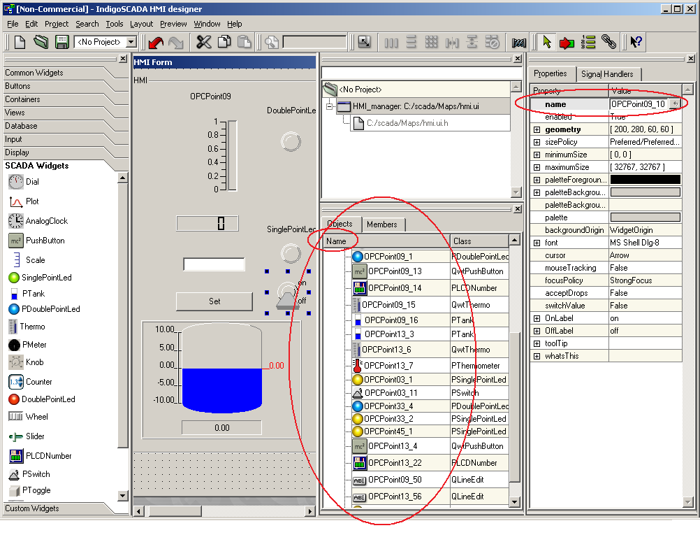
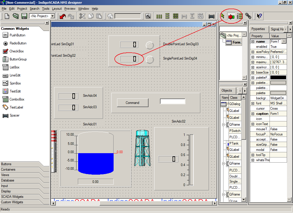
HMI configuration with HMI designer
10 - Run the process C:\scada\bin\hmi_designer.exe
11 - Create from scratch your HMI (dialog) and save it as hmi0.ui in C:\scada\project
12 - Use the following widget classes
| Widget | Class
|
| SINGLE POINT LED | PSinglePointLed
|
| DOUBLE POINT LED | PDoublePointLed |
| SINGLE POINT LED | SinglePointLed |
| DOUBLE POINT LED | DoublePointLed
|
| SWITCH | PSwitch
|
| THERMOMETER | QwtThermo
|
| LCD NUMBER | PLCDNumber |
| COMMAND BUTTON | QPushButton |
| TANK | PTank |
| THERMOMETER | PThermometer |
| EDIT FIELD | QLineEdit |
| BREAKER | Breaker |
13 - Widget names MUST contain the underscore _ as separator between sample point SCADA name and widget ID
For example the widget with SCADA name MQTTSample09 and ID 1 has full name: MQTTSample09_1
Please see next image 1
1
|
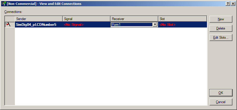
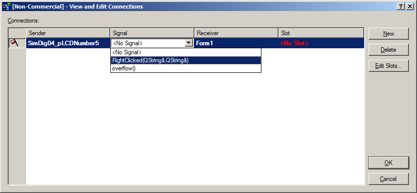
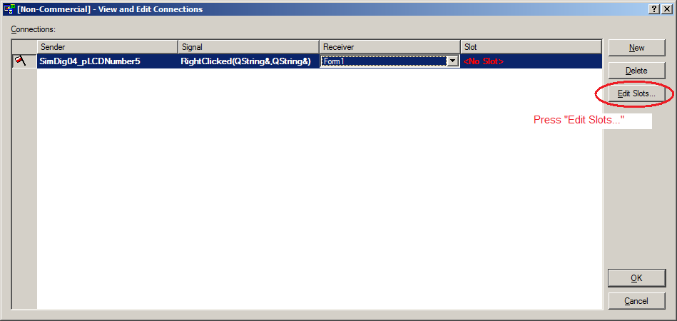
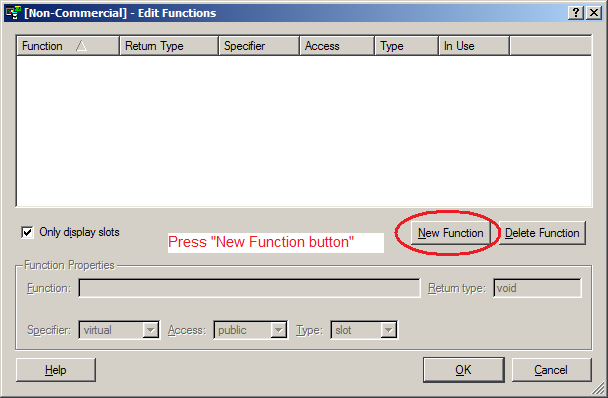
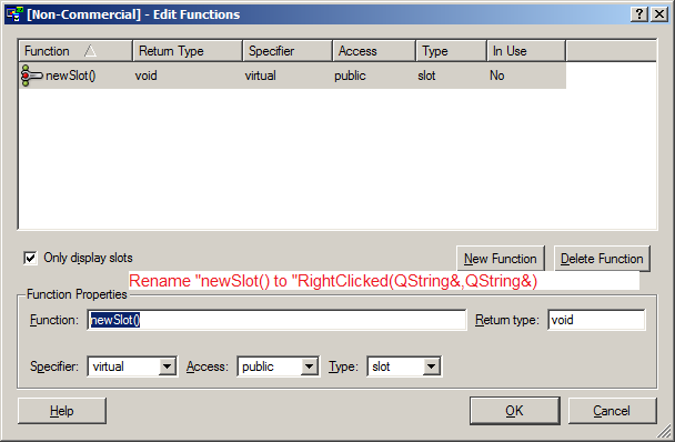
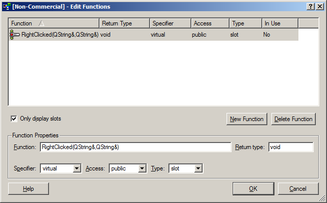
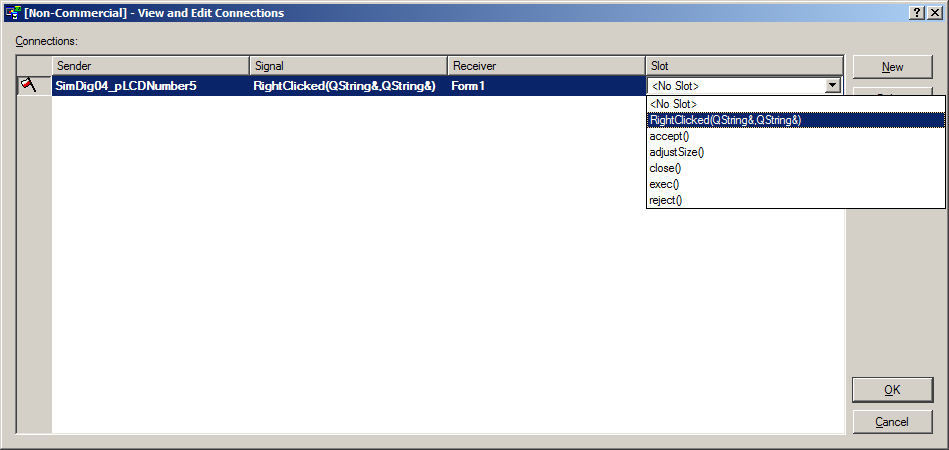
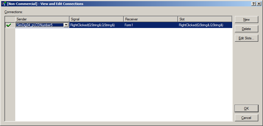
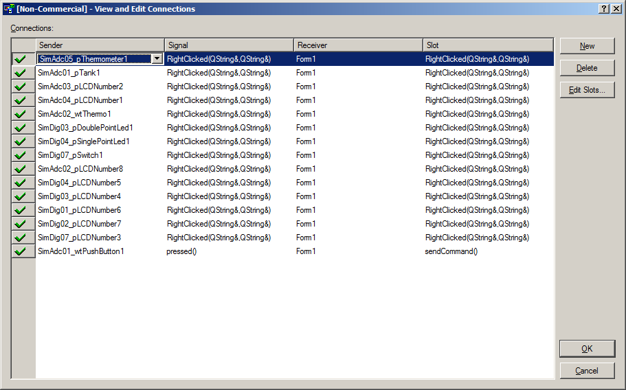
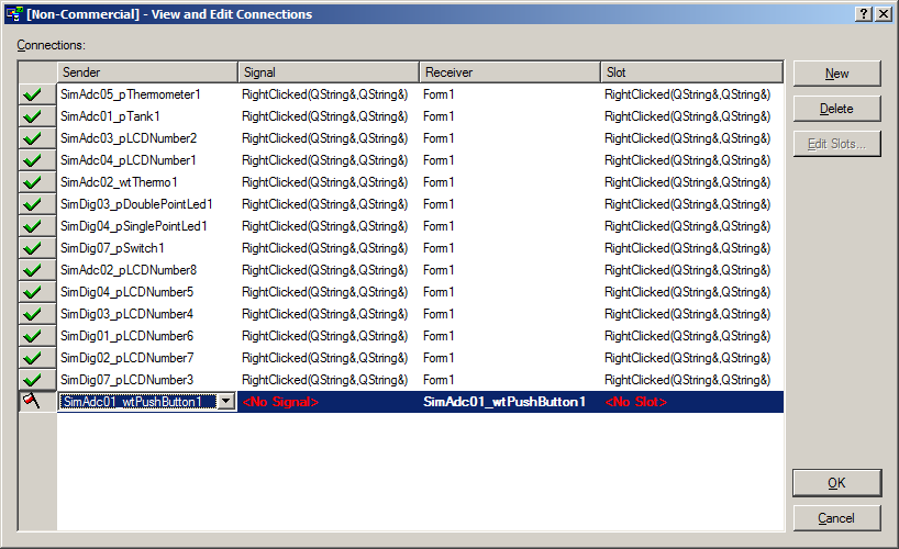
14 - To enable the inspect popup window, please follow the procedure:
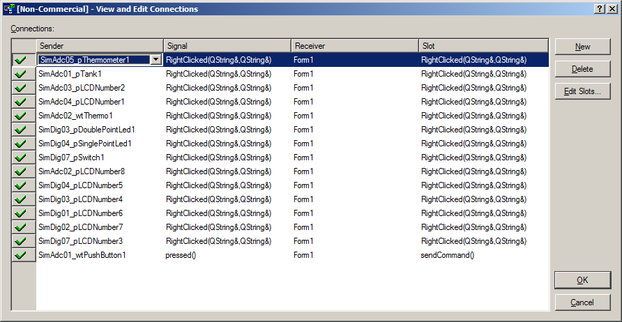
You have to connect the signals RightClicked(QString&,QString&) of the widgets with the slot RightClicked(QString&,QString&) of the HMI dialog (here Form1)
Step 1
|
Step 2
|
Step 3
|
Step 4
|
Step 5
|
Step 6
|
Step 7
|
Step 8
|
Step 9
|
Final result
|
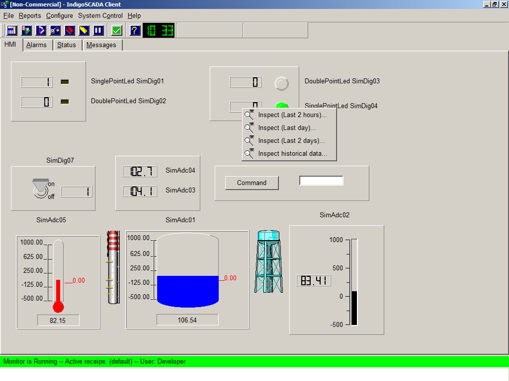
Working popup on HMI
|
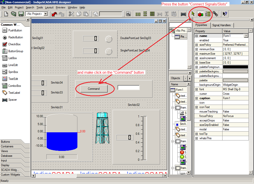
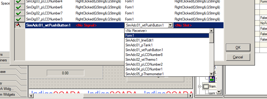
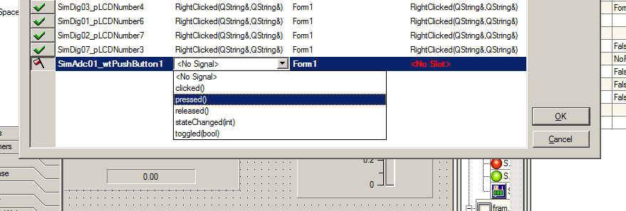
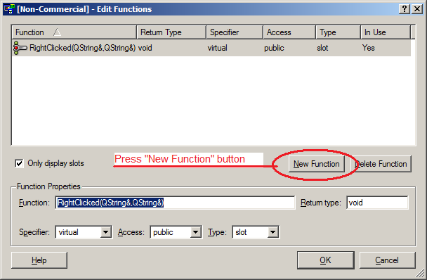
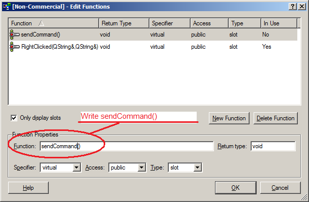
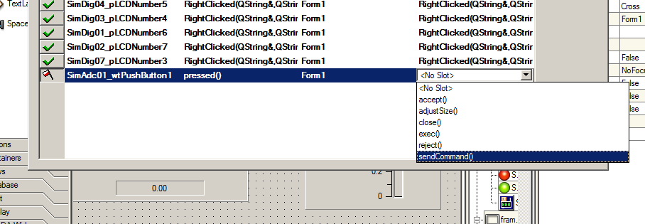
15 - To enable commands, please follow the procedure:
Step 1
|
Step 2
|
Step 3
|
Step 4
|

Step 5
|
Step 6
|
Step 7
|
Step 8
|
Step 9
|
|