logo
You are in: Master IEC 101 Protocol Configuration Section  Home   Products & Services   Links   Contacts   Legal   What's new? 


Master IEC 101 Protocol Configuration Section


This procedure applies to latest revision.

This driver is made by the two modules: iec101driver.dll and iec101master.exe

Creation of the new points

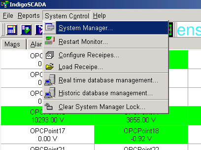
1 - Select the menu: System Control\System Manager

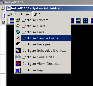
2 - Select the menu: Configure\Configure Units

3 - Press button New

4 - Fill in the edit field Name: IEC101

5 - Select Type iec101driver, flag Unit Enabled and press Configure button

6 - Fill in the IEC 101 slave link address, number of points

7 - Press button Apply, wait that the Apply button return active and then press Exit

8 - Restart monitor.exe

Add the new points to HMI

9 - Select the menu: Configure\Configure Sample Points

10 - Set Comment, Type, Units and the limits of each new point. Press button Apply

- Set type M_SP_TA_1 for digital points

- Set type M_ME_TC_1 for analog points

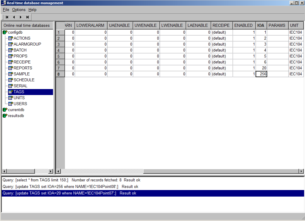
11 - Open table TAGS of real time DB

12 - Configure IOA of every point

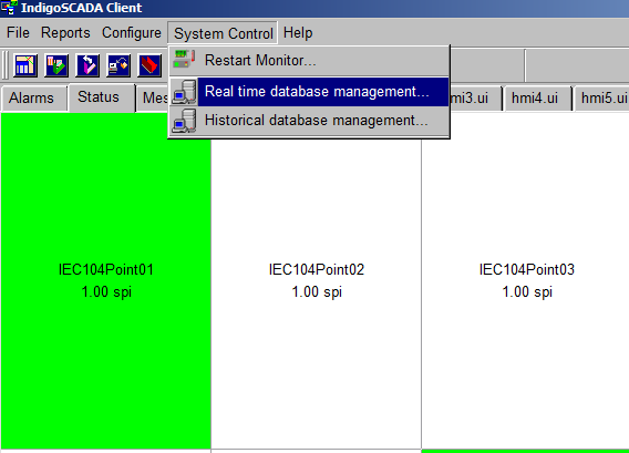
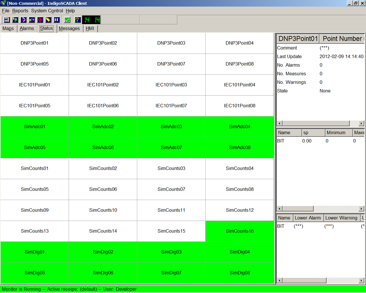
13 - New IEC101 sample points are visible and are updated with the values coming from the IEC 101 slave.

Immagine01.png
1
Immagine02.png
2
Immagine03.png
3
Immagine30.png
4
Immagine31.png
5
Immagine32.png
6
Immagine31.png
7
Immagine07.png
8
Immagine08.png
9
Immagine33.png
10
OpenRealTimeDB.png
11
ConfigureIOA.png
12
Immagine34.png
13
Image nameImageInternal SCADA valueComment
single0000.png single0000.png0Green means state off
single0001.png single0001.png1Red means state on
single0002.png single0002.png2Yellow is not used for Single point
single0003.png single0003.png3Yellow is not used for Single point
single0004.png single0004.png4White means HMI state none or Invalid
single0005.png single0005.png5Blue means Communication driver error state or Invalid


Image nameImageInternal SCADA valueComment
double0000.png double0000.png0Yellow means Indeterminate or Intermediate state
double0001.png double0001.png1Green means Determinate state off
double0002.png double0002.png2Red means Determinate state on
double0003.png double0003.png3Yellow means Indeterminate state
double0004.png double0004.png4White means HMI state none or Invalid
double0005.png double0005.png5Blue means Communication driver error state or Invalid


© 2002-2012 Enscada  

Locations of visitors to this page


Large Visitor Map