Master DNP 3.0 Protocol Configuration Section

This procedure applies to latest revision.
This native driver is made by the two modules: dnp3driver.dll and dnp3master.exe
dnp3master.exe is the protocol implementation, while dnp3driver.dll is a bridge with monitor.exe process.
dnp3driver.dll and dnp3master.exe are loaded automatically by monitor.exe when you configure a new unit of type DNP3
Creation of the new points
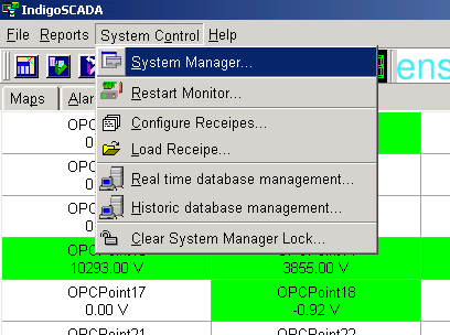
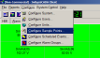
1 - Select the menu: System Control\System Manager
2 - Select the menu: Configure\Configure Units or "SCADA line"
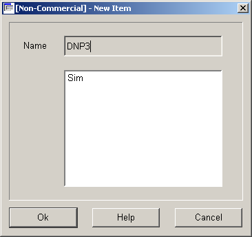
3 - Press button New
4 - Fill in the edit field Name: DNP3 or a name containing the word DNP3, e.g. DNP3A, DNP3B, ...
5 - Select Type dnp3driver, flag Unit Enabled and press Configure button
6 - Fill in ServerID (the slave link address), DNP 3.0 slave IP address, TCP port of slave (e.g 20000 is the default), first IOA for AI, first IOA for BI, first IOA for CI, first IOA for BO, first IOA for AO, number of points and master polling time
6a - Where "first IOA for AI = 1", "first IOA for BI = number of AI + 1", "first IOA for CI = number of AI + number of BI + 1", "first IOA for BO = number of AI + number of BI + number of CI + 1", "first IOA for AO = number of AI + number of BI + number of CI + number of BO + 1"
7 - Press button Apply, wait that the Apply button return active and then press Exit
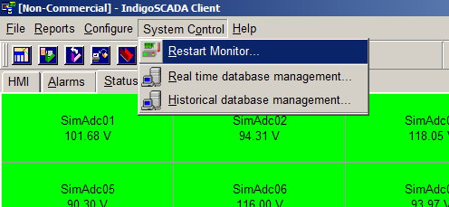
8 - Restart monitor.exe
Add the new points to HMI
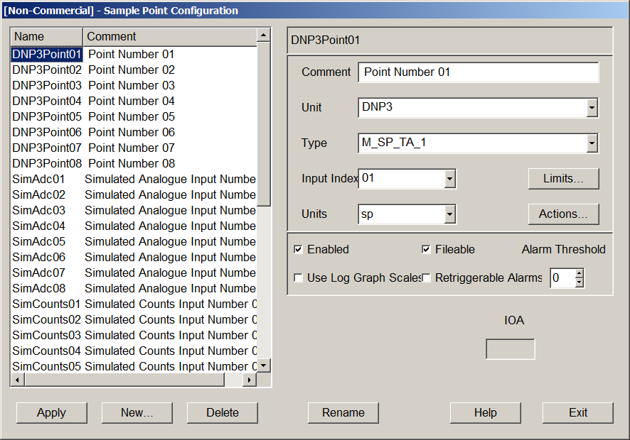
9 - Select the menu: Configure\Configure Sample Points
10 - Set Comment, Type, Units and the limits of each new point. Press button Apply
- Set type M_SP_TB_1 for digital points
- Set type M_ME_TC_1 for analog points
9
|

10
|
HMI configuration with HMI designer
10 - Run the process C:\scada\bin\hmi_designer.exe
11 - It is possible to create from scratch your HMI (dialog) and save it in C:\scada\project
12 - Use the following widget classes
| Widget | Class
|
| SINGLE POINT LED | PSinglePointLed
|
| DOUBLE POINT LED | PDoublePointLed |
| SINGLE POINT LED | SinglePointLed |
| DOUBLE POINT LED | DoublePointLed
|
| SWITCH | PSwitch
|
| THERMOMETER | QwtThermo
|
| LCD NUMBER | PLCDNumber |
| COMMAND BUTTON | QPushButton |
| TANK | PTank |
| THERMOMETER | PThermometer |
| EDIT FIELD | QLineEdit |
| BREAKER | Breaker |
13 - Widget names MUST contain the underscore _ as separator between sample point SCADA name and widget ID
For example the widget with SCADA name DNP3Sample09 and ID 1 has full name: DNP3Sample09_1
Please see next image 1
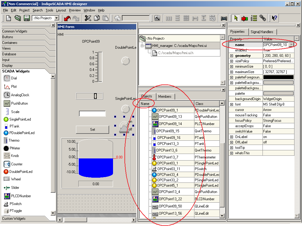
1
|
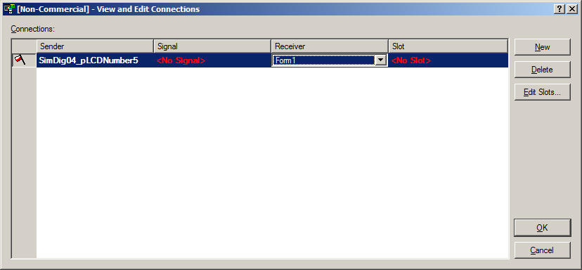
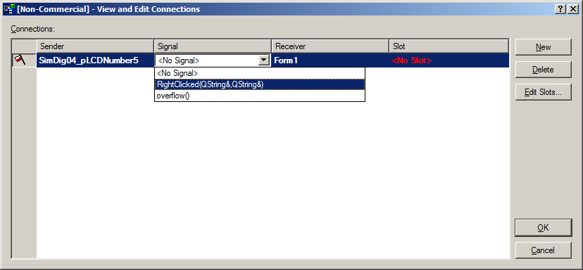
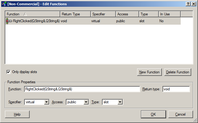
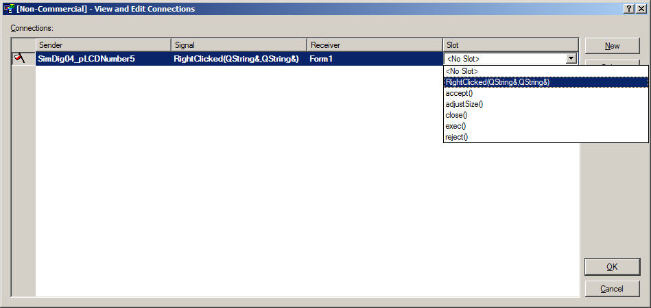
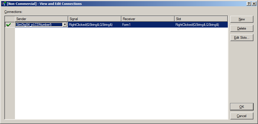
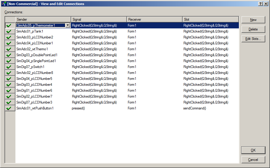
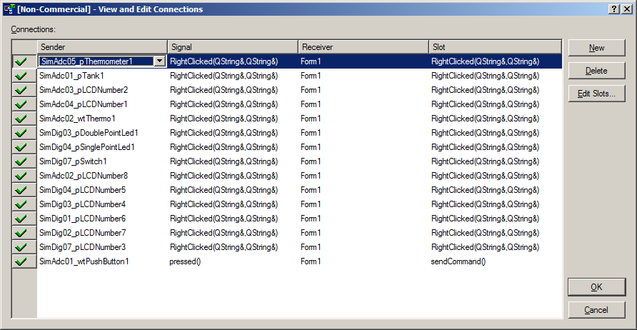
14 - To enable the inspect popup window, please follow the procedure:
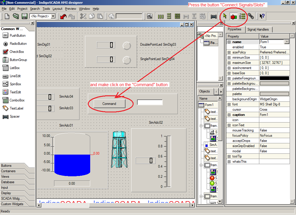
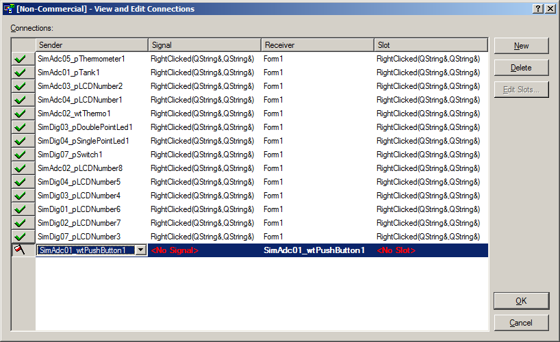
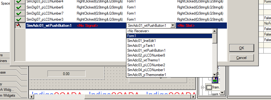
You have to connect the signals RightClicked(QString&,QString&) of the widgets with the slot RightClicked(QString&,QString&) of the HMI dialog (here Form1)
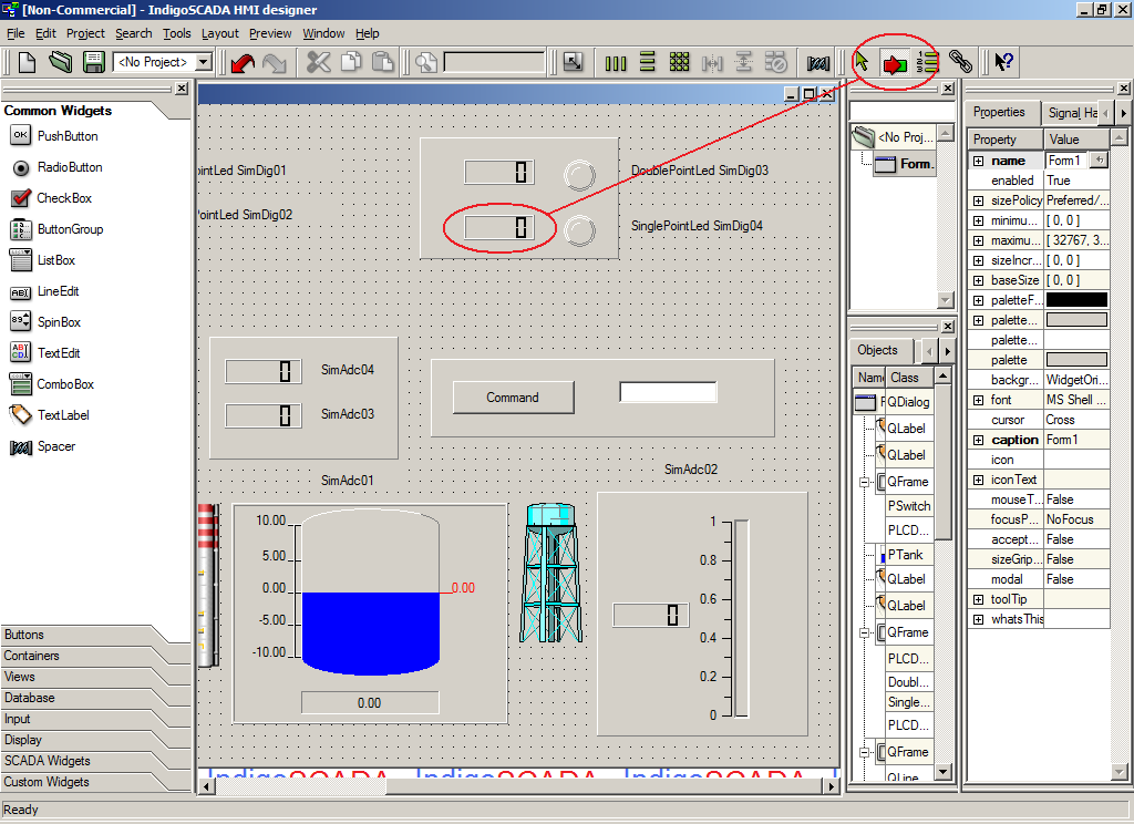
Step 1
|
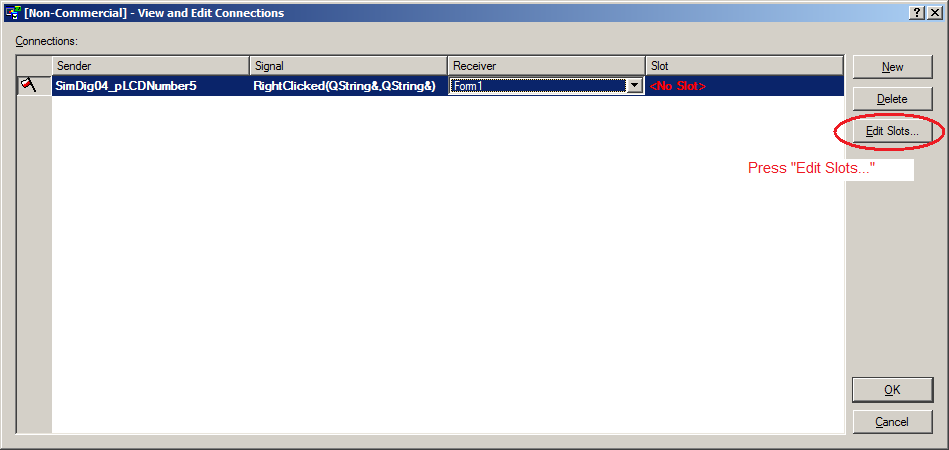
Step 2
|
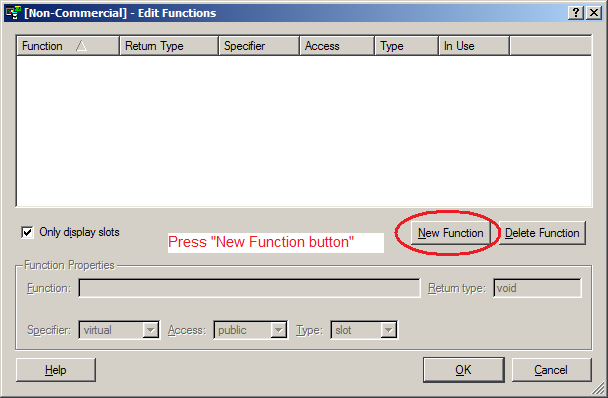
Step 3
|
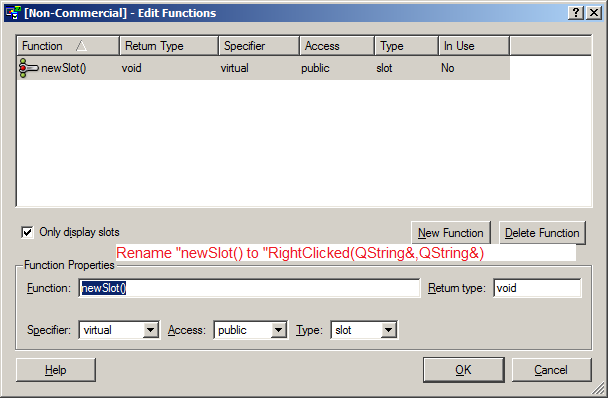
Step 4
|
Step 5
|
Step 6
|
Step 7
|
Step 8
|
Step 9
|
Final result
|
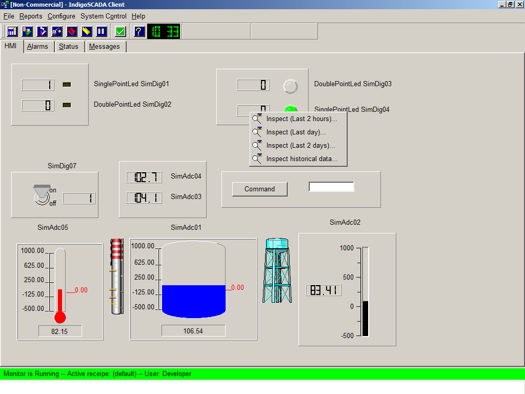
Working popup on HMI
|
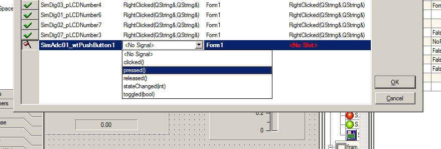
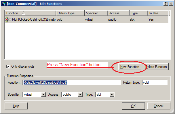
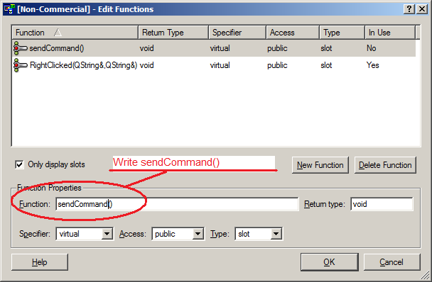
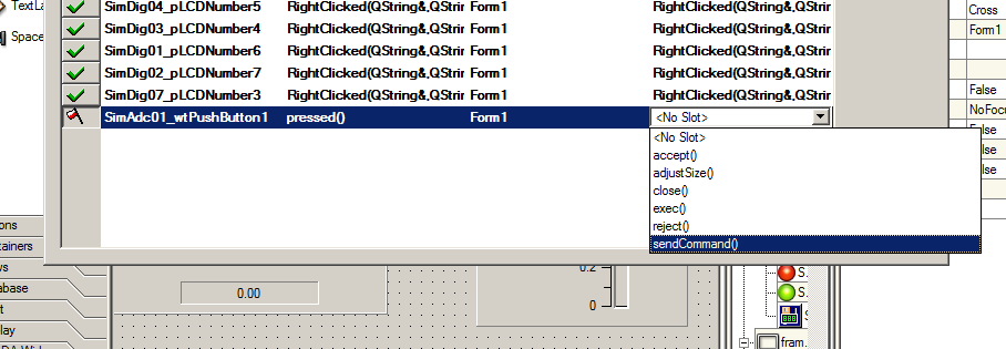
15 - To enable commands, please follow the procedure:
Step 1
|
Step 2
|
Step 3
|
Step 4
|

Step 5
|
Step 6
|
Step 7
|
Step 8
|
Step 9
|
|